Shoreline & Streambank Stabilization Rule
Download the full Shoreline & Streambank Stabilization Rule PDF.
Adopted April 24, 2014
Effective June 6, 2014
1. POLICY
It is the policy of the Board of Managers to:
(a) Preserve the natural appearance of shoreline and streambank areas;
(b) Encourage and foster bioengineering, landscaping and preservation of natural vegetation as preferred means of stabilizing shorelines and streambanks;
(c) Assure that improvement of shoreline and streambank areas to prevent erosion complies with accepted engineering principles in conformity with Minnesota Department of Natural Resources construction guidelines; and
(d) Preserve water quality and the ecological integrity of the riparian environment, including wildlife, fisheries, and recreational water resources.
2. REGULATION
(a) No person shall install an improvement or alteration of the shoreline of a water basin or the bank of a watercourse, including but not limited to a bioengineered installation, riprap, a retaining wall, a sand blanket or a boat ramp, without first securing a permit under this rule and providing a financial assurance pursuant to the District Financial Assurance Rule. Planting of vegetation not intended to provide deep soil structure stability does not require a permit under this rule.
(b) All permit applications submitted under this rule, except applications for maintenance of an existing improvement that has not degraded to a natural state, shall be required to include a detailed erosion intensity calculation of the shoreline or streambank in accordance with section 3, Shoreline Erosion Intensity Calculation (for shorelines), or section 4, Streambank Erosion Intensity Calculation (for streambanks), of this rule.
(c) A permit under this rule is required for maintenance of an existing riprap or otherwise hard-armored shoreline or streambank that involves the addition of new material or structural change to the improvement. No permit under this rule is required for maintenance of an existing shoreline or streambank improvement that involves in-kind replacement or restoration of the improvement in compliance with the criteria in this rule.
(d) A Fast Track permit may be issued for shoreline stabilization projects that conform to the requirements in section 6, Criteria for Stabilization Techniques, of this rule.
(e) Shoreline or streambank stabilization projects that do not utilize a stabilization practice consistent with the erosion intensity calculation shall be required to document compliance with the design flexibility/minimal impact standard in section 5, Design Flexibility. Such projects shall be subject to the public notice requirements of the District Procedural Requirements Rule.
(f) A Fast Track permit may be issued for routine sand blanket projects that conform to the requirements set forth in sections 8, Criteria for Laying Sand blankets, and 9, Sand blankets Required Exhibits, of this rule.
3. SHORELINE EROSION INTENSITY CALCULATION
(a) Applications for shoreline stabilization shall be required to complete the Erosion Intensity Scoresheet to document the shoreline erosion intensity (low, medium, high). The Erosion Intensity Scoresheet will be maintained and periodically updated to account for changing conditions and improved understanding of shoreline erosion factors and approved by the Board of Managers by resolution. (The current Erosion Intensity Scoresheet may be obtained from the District office or online.)
(b) The proposed shoreline stabilization practice shall be consistent with the shoreline erosion intensity calculated (low, medium, high).
(1) Low erosion intensity shorelines shall utilize biological stabilization practices in accordance with section 6, Criteria for Stabilization Techniques, of this rule.
(2) Medium erosion intensity shorelines shall utilize biological or bioengineering stabilization practices in accordance with section 6, Criteria for Stabilization Techniques, of this rule.
(3) High erosion intensity shorelines shall utilize biological, bioengineering or structural stabilization practices in accordance with section 6, Criteria for Stabilization Techniques, of this rule.
4. STREAMBANK EROSION INTENSITY CALCULATION
(a) Applications for streambank stabilization shall be required to complete and report the calculations detailed below to document bank-ful stream velocity and shear stress:
- Bankful stream velocity
- i. Manning’s equation:
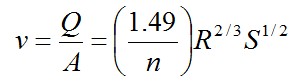
- v = Average velocity of flow (feet/sec)
- Q = Bankful flow (cubic feet/sec)
- A = Area of flow (square feet)
- n = Manning’s number
- R = Hydraulic radius (feet)
- S = Slope of channel bottom (rise/run)
- v = Average velocity of flow (feet/sec)
- Q = Bankful flow (cubic feet/sec)
- A = Area of flow (square feet)
- n = Manning’s number
- R = Hydraulic radius (feet)
- S = Slope of channel bottom (rise/run)
- i. Manning’s equation:
- Shear stress on the streambank
- i.
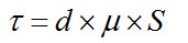
- τ = Shear stress (pounds / square feet)
- d = Bankful flow depth (feet)
- μ = Unit weight of water (62.4 pounds / cubic feet)
- S = Slope of channel bottom (rise/run)
- τ = Shear stress (pounds / square feet)
- d = Bankful flow depth (feet)
- μ = Unit weight of water (62.4 pounds / cubic feet)
- S = Slope of channel bottom (rise/run)
- i.
(b) The proposed streambank stabilization practice shall be consistent with the shear stress calculated (low, medium, high).
- Low erosion intensity streambanks are those where the shear stress calculated is less than or equal to 2.5 lb per square foot and shall utilize biological stabilization practices in accordance with section 6, Criteria for Stabilization Techniques, of this rule.
- Medium erosion intensity streambanks are those where the shear stress calculated is between 2.5 and 5 lb per square foot and shall utilize biological or bioengineering stabilization practices in accordance with section 6, Criteria for Stabilization Techniques, of this rule.
- High erosion intensity streambanks are those where the shear stress calculated is greater than 5 lb per square foot and shall utilize biological, bioengineering or structural stabilization practices in accordance with section 6, Criteria for Stabilization Techniques, of this rule.
5. DESIGN FLEXIBILITY
Where an applicant believes that, as a result of site specific conditions, the shoreline erosion intensity as calculated in section 3, Shoreline Erosion Intensity Calculation, or the streambank erosion intensity as calculated in section 4, Streambank Erosion Intensity Calculation, may inaccurately predict the degree of erosion, the District may approve alternative stabilization techniques if the applicant provides sufficient evidence to demonstrate that the proposed stabilization practice represents the minimal impact solution with respect to all other reasonable alternatives.
6. CRITERIA FOR STABILIZATION TECHNIQUES
(a) General criteria:
- The District will permit the installation of structural stabilization practices only where there is a demonstrated need to prevent erosion or to restore eroded shoreline/streambank;
- Removal of native vegetation within the shoreline/streambank stabilization zone shall be limited in accordance with the following provisions:
- i. Clear cutting shall be prohibited except within the access corridor;
- ii. Native vegetation shall be preserved outside of the access corridor as much as practicable and, where removed, shall be replaced with other vegetation that is equally effective in retarding runoff and preventing erosion.
- Stabilization practices shall be installed at a 3:1 slope or flatter where practical and feasible. Practices proposed at slopes steeper than 2:1 shall be evaluated as retaining walls in accordance with section 10, Criteria for Retaining Walls, of this rule;
- Horizontal encroachment from a shoreline shall be the minimum amount needed and shall not interfere unduly with water flow. Under normal conditions, hard armoring inert material, such as riprap, or other fill shall be placed no more than 5 feet waterward of a shoreline, measured from the OHW. The maximum encroachment waterward of the OHW is 10 feet. Encroachment from streambanks shall be minimized to the greatest extent practical to limit hydraulic impacts;
- Streambank stabilization shall not reduce the cross sectional area of the channel nor result in a net increase in the flood stage upstream or at the site of the streambank stabilization practice unless it can be demonstrated to not exacerbate existing high-water conditions;
- Shoreline/streambank stabilization practices shall conform to the natural alignment of the bank (e.g., maintain an undulating or meandering shoreline/streambank);
- The design shall reflect the engineering properties of the underlying soils and any soil corrections or reinforcements. For a shoreline, the design shall conform to engineering principles for dispersion of wave energy and resistance to deformation from ice pressures and movement. For a streambank, design shall conform to engineering principles for the hydraulic behavior of open channel flow;
- For sites involving aquatic plantings or aquatic plant removal, a separate Aquatic Plant Management permit shall be obtained from the Department of Natural Resources, when applicable;
- Any work below the ordinary high water level shall be encircled by a flotation sediment curtain. The curtain shall be constructed and maintained as illustrated in “Protecting Water Quality in Urban areas – Best Management Practices for Minnesota” (MPCA 2000). The barrier shall be removed upon completion of the work after disturbed sediment has settled;
- All shoreline/streambank stabilization applications shall submit the required exhibits as set forth in section 7, Required Exhibits for Shoreline/Streambank Stabilization, of this rule.
(b) Criteria for biological and bioengineering techniques:
- Live plantings incorporated into the shoreline or bank shall be native aquatic and/or native upland vegetation known to occur in the North Central Hardwood Forest eco-region of Minnesota (refer to the Minnesota Department of Natural Resources “Lakescaping for Wildlife and Water Quality” and the Minnesota Pollution Control Agency “Plants for Stormwater Design”);
- Vegetative treatments shall be installed in accordance with the Natural Resource Conservation Service “Engineering Field Handbook Chapter 16”;
- If wave barriers are utilized, they shall be located within the 3 foot water depth or less and may not create an obstruction to navigation. Wave barriers shall be removed within 2 years of the installation.
- Bioengineered stabilization also must comply with the criteria in (c)(1) – (3) and (5).
(c) Criteria for structural stabilization:
- Hard armoring inert material, such as riprap, shall be considered wetland fill only if proposed to be placed within an area identified as a wetland;
- Riprap shall extend no higher than the top of the bank, or two feet above the 100-year high water elevation, whichever is lower;
- Riprap materials shall be durable stone meeting the size and gradation requirements of MnDOT Class III or IV riprap. Toe boulders shall be at least 50 percent buried and may be as large as 30 inches in diameter;
- A transitional granular filter meeting requirements of MnDOT 3601.B, at least 6 inches in depth, shall be placed between the native shoreline and the riprap to prevent erosion of fine grained soils. A geotextile filter fabric meeting the requirements of MnDOT 3733 shall be placed beneath the granular filler where appropriate;
- Structural stabilization practices, including riprap, are recommended to include plantings between individual boulders or native upland plantings to retard runoff and prevent erosion wherever feasible and practical.
7. REQUIRED EXHIBITS FOR SHORELINE/STREAMBANK STABILIZATION
(a) Erosion intensity calculations from section 3, Shoreline Erosion Intensity Calculation, or 4, Streambank Erosion Intensity Calculation, of this rule, whichever is applicable, or materials necessary to make the demonstration required in section 5, Design Flexibility.
(b) Photographs of the project site, showing existing conditions.
(c) Site plan showing:
- Survey locating the existing ordinary high water (OHW) elevation, existing shoreline or streambank, 100-year high water elevation, and location of property lines;
- Elevation contours of the upland within 15 feet of the OHW and referenced to accepted datum;
- Location of the shoreline/streambank stabilization zone and access corridor;
- Location of existing trees and shrubs within the shoreline/streambank stabilization zone and an indication of whether they are to be removed or retained;
- Plan view of locations and lineal footage of the proposed shoreline/bank stabilization treatment; and
- The location of an upland baseline parallel to the shoreline/bank with stationing. The baseline shall be staked in the field and maintained in place until project completion. Baseline origin and terminus each shall be referenced to three fixed features, with measurements shown and described on the plan. Perpendicular offsets from the baseline to the OHW shall be measured and distances shown on the plan at 20 foot stations.
(d) Cross section, drawn to scale, with the horizontal and vertical scales noted on the drawing, detailing:
- The existing bank, OHW, and 100-year high water elevation;
- The proposed stabilization technique, finished slope, and distance lakeward of the OHW;
- Material specifications;
- Description of the underlying soil materials.
(e) Specification of erosion control and site stabilization practices.
(f) For biological and bioengineering stabilization practices, a Vegetation Establishment Plan, including:
- A plant list with common and scientific names, seed mix specifications, quantities and origin of all material; and
- Specification of the methods, schedule and party responsible for ensuring establishment and maintenance of the vegetation for the three years following installation or construction. The plan shall include the control of invasive species and replacement of vegetation as necessary.
(g) For bioengineering:
- Detail the location of all hard armoring inert material, such as riprap, to be utilized;
- Provide a written narrative explaining how the use of hard armoring inert material such as riprap has been minimized to the extent practical and feasible.
(h) For streambank stabilization:
- Cross sectional view of stream channel in existing and proposed conditions;
- Longitudinal view of stream channel in existing and proposed conditions;
- Plan view of stream channel in existing and proposed conditions;
- Identification of bankful indicators;
- Documentation of existing soils, wetlands, vegetation, slopes, bank and channel material;
- Identification of in-stream features such as woody debris, riffles and pools, etc.
(i) For sites involving aquatic plantings or aquatic plant removal, a copy of the Department of Natural Resources Aquatic Plant Management permit application, if required.
8. CRITERIA FOR LAYING SAND BLANKETS
All permitted sand blanketing shall comply with the following standards:
(a) The sand or gravel used must be clean prior to being spread. The sand must contain no toxins or heavy metal, as defined by the Minnesota Department of Natural Resources, and must contain no weed infestations such as, but not limited to, water hyacinth, alligator weed, and Eurasian watermilfoil, or animal life infestations such as, but not limited to, zebra mussels or their larva. Violators will be prosecuted to the full extent of the law.
(b) The sand layer must not exceed six inches in thickness, 50 feet in width along the shoreline, or one-half the width of the lot, whichever is less, and may not extend more than 10 feet waterward of the ordinary high water mark.
(c) Only one installation of sand or gravel to the same location may be made during a four-year period. After the four years have passed since the last blanketing, the location may receive another sand blanket. No more than two applications may be made at an individual project site.
(d) Exception. Beaches which are operated by governmental entities and available to the public shall be maintained in a manner that represents the minimal impact to the environment, relative to other reasonable alternatives, and but otherwise are exempt from the criteria in paragraphs (b) and (c) of this section.
9. SAND BLANKET REQUIRED EXHIBITS
The following exhibits shall accompany the sand blanket permit application:
(a) Site plan showing property lines, delineation of the work area, existing elevation contours of the adjacent upland area, ordinary high water elevation, and 100-year high water elevation (if available). All elevations must be reduced to NGVD (1929 datum).
(b) Profile, cross sections and/or topographic contours showing existing and proposed elevations in the work area. (Topographic contours should be at intervals not greater than 1.0 foot).
(c) A completed Sand blanket Permit Application form, available from the District.
10. CRITERIA FOR RETAINING WALLS
(a) A new retaining wall, or repair/reconstruction of an existing retaining wall that increases floodplain encroachment beyond that required by technically sound and accepted repair/reconstruction methods, is permitted only pursuant to a variance or an exception under the District Variance Rule. The applicant must demonstrate that there is no adequate stabilization alternative.
(b) Wooden seawalls and/or steel sheetpiling retaining walls shall comply with accepted engineering principles.
(c) The applicant shall submit a structural analysis prepared by a professional engineer registered in the State of Minnesota, in the practice of civil engineering, showing that the wall will withstand expected ice and wave action and earth pressures.
(d) The applicant shall submit a survey prepared by a registered land surveyor locating the finished wall and shall file a certificate of survey with the District.
11. CRITERIA FOR OTHER SHORELINE IMPROVEMENTS
Other shoreline improvements, such as boat ramps, shall comply with accepted engineering principles as follows:
(a) Boat ramps and other similar improvements shall not be allowed in riparian shoreline areas unless the applicant demonstrates that no feasible alternative riparian access is available, that aquatic habitat and water quality impacts are minimized;
(b) Installation of boat ramps shall involve placement of no more than 50 cubic yards of inert and clean material, and the maximum width of shoreline disturbance shall be 15 feet unless the facility is a commercial marina or public launch facility that requires a greater width; and
(c) Materials utilized for construction of boat ramps or other similar improvements shall be safe and cause no adverse environmental impacts; the improvement shall be of sound design and construction so that the improvement is reasonably expected to be safe and effective.
REVISIONS PURSUANT TO MINNESOTA STATUTES §103D.341
Regulations list:
- Definitions
- Illicit Discharge Rule
- Floodplain Alteration Rule
- Wetland Protection Rule
- Dredging Rule
- Shoreline & Streambank Stabilization Rule
- Appropriations Rule
- Waterbody Crossings & Structures Rule
- Stormwater Management Rule
- Procedural Requirements Rule
- Financial Assurances Rule
- Erosion Control Rule
- Enforcement Rule
- Variances and Exceptions Rule
- Fees Rule